5. The Rendering Pipeline and Event Handling
Introduction 1
- The rendering process converts a view of the graphics scene into lighted pixels on the monitor, allowing us to view the image.
- This is accomplished by rending the image via scanlines, a technique commonly used by computer graphics hardware.
- In our graphics system, the scanline is all of the pixels in our viewport that have the same value of Y.
- We use the term viewport because our graphics system is concerned about generating the image that maps to the 2-dimensional window that we are using to view the image. This window may or may not have the same dimensions as the resolution of our monitor!.
- The portion of the object that is visible and can be rendered is called a fragment.
- Rendering:
- It is the process of calculating and setting the intensity of red, green, and blue for each pixel in the fragment and doing so for each scan line in the output image.
- We refer to the rendering process as a pipeline because rendering involves multiple steps in the process.
- The output of one of these steps becomes the input to the next.
- Example:
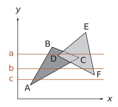
- The scanline is represented by the figure above.
- The graphics system would need to draw the pixels for the geometry D and the geometry C to render line
a. - In D, only a portion of the object is visible as a portion of the object is hidden behind C.
- Although the entire portion of the C object on the scanline a is visible and can be rendered, it is still referred to as a fragment.
- Graphic Loop:
- Graphics programs that incorporate motion are typically structured as having a graphics loop.
- The graphics loop continuously initiates the rendering process.
function animate() {
    requestAnimationFrame(animate);
    render();
}

function render() {
    cameraControls.update();
    renderer.render(scene, camera);
}

animate();
- Animate:
- RequestAnimationFrame:
- It is a function that is built into the browser that is used to initiate the rendering process.
- It takes a callback function as an argument.
- It tells the browser to call the callback function before the next repaint.
- After the
requestAnimationFramepushes an event to call itself in the queue; it calls therenderfunction. - Each time the animate function is executed, it schedules an event to execute animate again. Essentially this is continually refreshing the scene.
- As the scene undergoes transformations, the view is rendered again to represent the changes in geometry and lighting.
- This render loop is one example of the use of events within a graphics program.
- RequestAnimationFrame:
- Render:
- CameraControls.Update:
- Handles events from the mouse and allows users to interact with the scene.
- Renderer.Render:
- It is the function that actually renders the scene.
- It takes the scene and the camera as arguments.
- It calculates the color of each pixel in the scene and sets the color of the pixel in the output image.
- CameraControls.Update:
The Rendering Pipeline 2
- A series of steps that every image goes through to convert the mathematical representation of a scene along with materials, lights, and other things in the scene into something that is actually visible on the screen.
- Steps:
- Model space:
- Individual objects are defined in their own coordinate system.
- It includes vertices, and how they are connected to form faces.
- Modelling transformations are applied to the objects to place them into the world space.
- Grouping and lighting are also done in this space.
- World space:
- Objects are placed in the world where they are relative to each other.
- Viewing transformations are applied to the objects to place them into the camera’s space.
- Sometimes, this transformation is combined with the modelling transformation in the ModelView transformation.
- Grouping and light info are passed to the next stage.
- Eye space:
- Decide what can be seen from the camera’s point of view.
- Projection transformations are applied to the objects to place them into the screen space.
- Initial coloring, lighting, and shading are done in this space; hence, every pixel is colored (color may change later).
- Depth (z-value) is calculated for each pixel.
- Clipping is done to remove objects that are not visible.
- Grouping and light info are passed to the next stage.
- Screen space:
- Every point in the scene is mapped to a point on the screen (pixel).
- Other information for each point may include: position, depth, color, texture, normal vector, etc.
- Pixel space:
- The actual color of each pixel is calculated and lit.
- Model space:
- Rendering can happen:
- Software only: CPU does all the work.
- On Graphic Card: GPU does all the work.
- Two parts of the rendering pipeline:
- Geometry pipeline: transforms the vertices of the objects in the scene.
- Rendering pipeline: converts the transformed vertices into pixels on the screen.
Graphics Pipeline and Rasterization 3
- OpenGL and DirectX uses graphics hardware to accelerate the rendering process.
- The process of taking a triangle and figuring out which pixels it covers is called rasterization.
- Given a triangle’s vertices & extra info for shading, figure out which pixels to “turn on” to render the primitive.
- Compute illumination values to “fill in” the pixels within the primitive.
- At each pixel, keep track of the closest primitive (z-buffer)
- Ray casting vs. Rasterization:
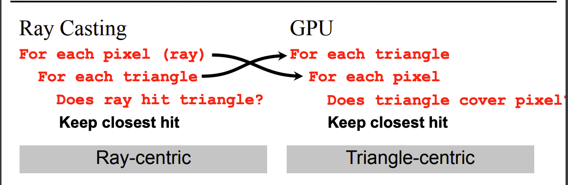
- Main difference:
- Ray casting requires the entire scene to be in memory before starting rendering.
- Rasterization only needs one triangle at a time.
- Rasterization advantages:
- A rasterization-based renderer can stream over the triangles, no need to keep entire dataset around.
- Allow parallelism and optimization of memory systems.
- Rasterization limitations:
- Restricted to scan-convertible primitives: triangles, lines, points.
- Faceting and shading artifacts are hard.
- No unified handling for shadows, reflections, and transparency.
- Overdrawing: high depth complexity: each pixel may be touched by many triangles, hence, being visited multiple times.
- Ray casting advantages:
- Generality: can handle any surface representation that can be ray-traced (intersected with a ray).
- Easily allows recursion: shadows, reflections, transparency are easier.
- Ray casting limitations:
- Slower: must intersect rays with all primitives in the scene.
- Relatively hard to implement on graphics hardware.
- Modern graphics pipeline:
- Project vertices to 2D screen space.
- Rasterize triangles: determine which pixels should be filled.
- Test visibility: depth test using z-buffer; update frame buffer if necessary.
- Compute per-pixel color: lighting, shading, texturing.
- SuperSampling:
- Rasterization can be improved by super-sampling.
- Instead of one sample per pixel, multiple samples are taken.
- Each sample is tested for visibility.
- The final pixel color is the average of all visible samples.
- Super-sampling can reduce aliasing artifacts.
References
-
Learning Guide Unit 5: Introduction | Home. (2024). Uopeople.edu. https://my.uopeople.edu/mod/book/view.php?id=444286&chapterid=540608 ↩
-
Unit 5 Lecture 1: The Rendering Pipeline | Home. (2024). Uopeople.edu. https://my.uopeople.edu/mod/kalvidres/view.php?id=444292 ↩
-
Massachusetts Institute of Technology (2020). Coordinates and Transformations. MITOpenCourseware. https://ocw.mit.edu/courses/electrical-engineering-and-computer-science/6-837-computer-graphics-fall-2012/lecture-notes/. Read Lecture #21, 22: Graphics Pipeline and Rasterization.
↩