2. Principles of Graphics Modeling
Introduction 1
- Vertex: a point in space that can be illuminated (e.g., the corners of a square).
- Line Segment: a line connecting two vertices (e.g. the left and right edges of a square).
- Polygon: a collection of connected line segments forming a closed shape (e.g., square, triangle, etc.).
- Polyhedron: a collection of polygons forming a closed shape in the 3D space as they share some edges (e.g., cube, pyramid, etc.).
- Mesh: A collection of 1 or more polygons formed of vertices and grouped together to form a 3D object (e.g., a cube made of 6 polygons).
- Transformations:
- Rotation: changing the orientation of an object.
- Scale: changing the size of an object.
- Position: changing the location of an object.
- Shading: drawing a surface over an object with material properties (e.g., color, texture, etc.).
Computer Graphics through OpenGL: From Theory to Experiments 2
Unit 2: Picture Transformation 3
- World coordinates: Dimensional coordinates that define the location of objects in the real world.
- Viewpoint (Camera) coordinates: The coordinates are based upon the viewpoint of the observer, and changes as they change their view.
- Screen coordinates: Physical coordinates of the pixels on the computer screen, based on current screen resolution.
- Transform: Changing some graphics into something else by applying rules.
- Translation: Shifting of a point to some other place, whose distance with regard to the present point is known.
- Rotation: Rotation of a point about an axis.
- Scaling: Increasing or decreasing the size of a picture in one or either directions.
- Matrix Representation of Points:
- A screen is a matrix of pixels, and each pixel has a unique address.
- An image can be thought as a matrix of the address of the pixels that are lit to form the image.
- Each point is represented by 3 components: x, y, and the method of representation (usually 1).
- Types of transformations:
- Appearance: changing the texture, color, surface, etc.
- Geometric:
- Changing the shape, size, orientation, etc.
- They are mathematical operations applied on the matrix representation of the object that results in a new matrix.
| Transformation | Description | Operation |
|---|---|---|
| Translation (Tx, Ty) | Moving an object from one place to another. | x’ = x + Tx; y’ = y + Ty. |
| Rotation (θ) | Changing the orientation of an object. | x’ = x.cosθ + y.sinθ, y’ = x.sinθ - y.cosθ. |
| Scaling (Sx, Sy) | Changing the size of an object. | x’ = x.Sx; y’ = y.Sy. |
- Viewing Pipeline:
- It is a series of transformations that are applied on the geometry of an image to end up as a 2D image on the screen.
- Pictures need to be “fitted” on the display device, and undergoes a series of transformations so that it can be displayed on the screen.
- Types of Coordinates:
- Model Coordinates: Coordinates of the created model in the infinite 3D space (e.g., Universe).
- World Coordinates: Coordinates of parts of the model that our objects may live in (e.g., Planet Earth).
- Viewing Coordinates: Coordinates of the model that are visible to the observer (e.g., a country on Earth).
- Normalized Coordinates: Normalizing viewing coordinates to a common scale to get device independent coordinates.
- Device Coordinates: Mapping the normalized coordinates into the current device’s physical coordinates.
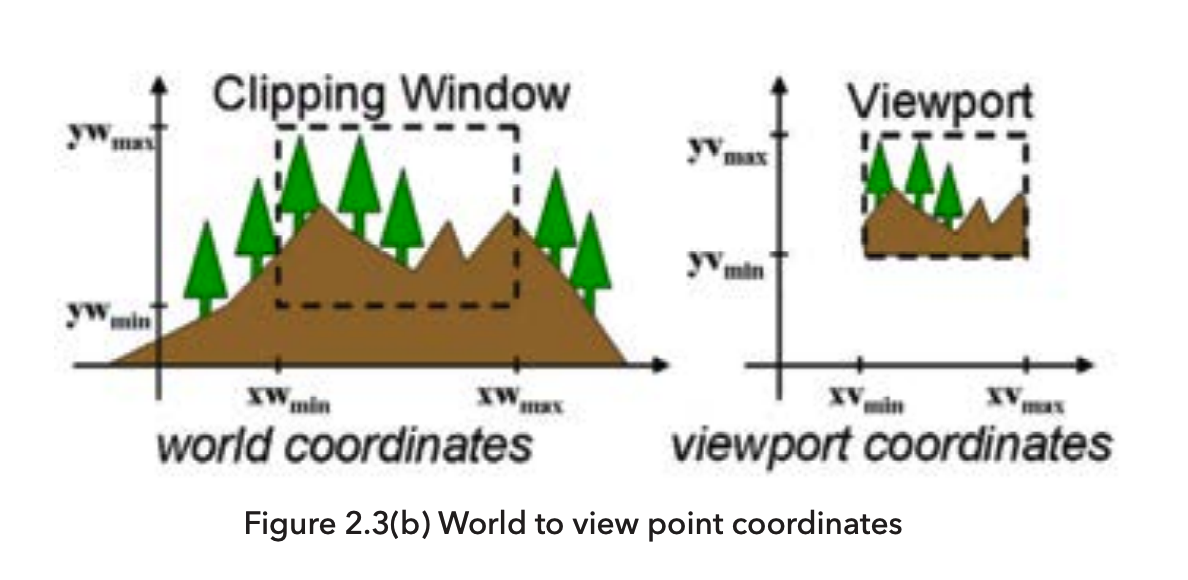
- Window-ViewPort Transformation:
- It describes the mapping of a (rectangular) window in one coordinate system into another (rectangular) window in another coordinate system.
Unit 3: Creating Graphics with OpenGL 3
- 3.1 OpenGL Fundamentals:
- OpenGL is independent of windowing characteristics of each operating system.
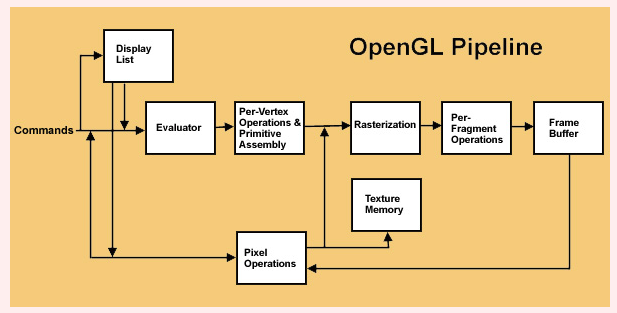
- Some commands are directly sent to the
Evaluator, while others are stored inDisplay Listsfor later dispatch in batch(es). Evaluatorprepares approximations of the curves and surface geometry by quickly evaluating some common functions.Per Vertex Operations and Primitive Assemblyis where the vertices are transformed and assembled into primitives, primitive are then clipped and prepared for rasterization.Rasterizationproduces frame buffer addresses for multiple fragments of the image, and those buffer frames are handed to the next stage.Per Fragment Operationsis where the fragments are processed to determine the final color of the pixel and stored into the Pixel Frame Buffer.- If the data does not include vertices, then it come in form of
Pixel Dataand is processed by thePixel Operationsstage. Such data usually comes as texture mapping, thus they skip theEvaluatorand get stored inTexture Memoryor may go through theRasterizationstage and update pixel color in thePixel Frame Buffer. - In both cases, OpenGL uses both
Frame BufferandTexture Memoryto store the final image.
- 3.2 Simple Drawings using OpenGL:
- Every graphics program begins with some initializations to establish the desired display mode and set up a coordinate system for specifying points, lines, etc.
- Simple graphics drawings use the Cartesian coordinate system with x and y coordinates representing pixels.
- Some functions from the OpenGL Utility Toolkit (GLUT) library:
glutInit(&argc, argv): Initializes the GLUT library.glutInitDisplayMode(mode): Sets the initial display mode as GLUT_SINGLE or GLUT_RGB.glutInitWindowSize(width, height): Sets the initial window size.glutInitWindowPosition(x, y): Sets the initial window position on the 2D screen surface.glutCreateWindow(name): Creates a window with the specified name.glutMainLoop(): Enters the GLUT event processing loop, which is an infinite loop that waits for events to occur, and then calls the appropriate event handler.glutMouseFunc((button, state, x, y)=>{/* handler*/}): Sets the mouse callback for the current window, aka, registers an event handler for mouse events such as mouse click, double click, etc.glutDisplayFunc(()=>{/* handler*/}): Sets the display callback for the current window, aka, registers an event handler for redraw events such as when window opened or moved.glutReshapeFunc(()=>{/* handler*/}): Sets the reshape callback for the current window, aka, registers an event handler for **reshape events**such as when window resized.glutKeyboardFunc((key, x, y)=>{/* handler*/}): Sets the keyboard callback for the current window, aka, registers an event handler for keyboard events such as key press or release.
- 3.3 Viewports, Mapping and Clipping:
- Viewport: A rectangular area on the screen where the graphics are displayed.
- Clipping: The process of removing the parts of the image that are outside the viewport.
- Window to Viewport Mapping: A series of transformations that converts world coordinates from the viewport to normalized and then device coordinates on the physical screen.
- Window: A rectangular area in the world coordinates (in units of whatever the world is measured in, e.g., meters).
- Viewport: A rectangular area in the device coordinates (in pixels).
- The mapping is done to scale the window to the viewport.
- Window is an imaginary concept to look at the world defined by the properties of the observing device (e.g., camera).
- Viewport is the actual area on the screen that looks at the window, and display its content to the user.
Coordinates and Transformations 4
- Vectors:
- A vector is a mathematical object that has both magnitude and direction (force and displacement).
- 0 Vector: No magnitude and no direction (no force and no displacement).
- Vectors allow for multiple operations such as addition, subtraction, multiplication, etc.
- Linear Transformations:
- A linear transformation is a function that maps a vector to another vector.
- Rotation: rotating a vector by an angle.
- Isotropic Scaling: scaling a vector by the same factor in all directions.
- Scaling: scaling a vector by different factors in different directions.
- Reflection: reflecting a vector about a line.
- Shear: sliding a vector in a direction.
- Translation is not a linear transformation because it does not preserve the origin.
- The table below defines some operations on vectors and points:
| Operation | Result | Formula | Description | Example |
|---|---|---|---|---|
| vector + vector | vector | \(\vec{v}+\vec{u}=\vec{r}\) | Adding two vectors | 3Km North + 4Km East = 5Km North-East |
| point + point | - | - | It does not make sense to add two points | - |
| scalar * vector | vector | \(c\vec{v}=\vec{r}\) | Scaling a vector by a scalar | 3 * 4Km North = 12Km North |
| \(\vec{0}\) + vector | vector | \(\vec{0}+\vec{v}=\vec{v}\) | Adding a zero vector to a vector | 0Km North + 4Km East = 4Km East |
| point - point | vector | \(\tilde{p} - \tilde{q} = \vec{v}\) | Subtracting two points | (3, 4) - (1, 2) = \(\vec{(2,2)}\) |
| point + vector | point | \(\tilde{p} + \vec{v} = \tilde{q}\) | Adding a point to a vector | (1, 2) + \(\vec{(3, 4)}\) = (4, 6) |
- Any point in the space is obtained by adding a vector to the origin (\(\tilde{o}\)) of the space.
- The last component:
- 1 => Point.
- 0 => Vector.
Chapter 5 - Three.js; A 3-D Scene Graph API 5
5.2 Building Objects
- Object = Geometry + Material.
- Polygonal Mesh:
- A collection of polygons, where the polygons can be joined together along their edges.
- A polygonal mesh can represent a polyhedron, or can be used as an approximation for a curved surface.
- A polygonal mesh can be represented as an indexed face set.
- If the polygons are small, the approximation can look like a curved surface.
- Indexed Face Set(IFS):
- A data structure that represents a polyhedron or polygonal mesh.
- The data structure includes a numbered list of vertices and a list of faces.
- A face is specified by listing the indices of the vertices of the face; that is, a face is given as a list of numbers where each number is an index into the list of vertices.
- A mesh is a representation of a 3D object using large number of polygons (triangles usually) stored in a data structure called Indexed Face Set (IFS), and has the necessary functions to manipulate and render the object.
- Geometry:
- It is an object of type
Three.BufferedGeometry. - Attributes:
position: stores the coordinates of the vertices of the object with each of them being aTypedArray.normal: stores the normal vectors of the vertices.color: stores the color of the vertices.
- Methods:
computeVertexNormals(): Computes the normal vectors of the vertices in the position attribute.addGroup(start, count, materialIndex): Adds a group of faces to the geometry. Wherestartis is the index of the first vertex in the position attribute,countis the number of vertices in the group, andmaterialIndexis the index of the material to be used for the group as the material used for the object must br an array of materials.setAttribute(name, value): Sets the attributes of the geometry.setIndex(value): Sets the index of Indexed Face Set.
- There are some specialized geometries that can be used to create some common 3D objects such as:
Three.BoxGeometry.Three.SphereGeometry.Three.CylinderGeometry.- etc.
- It is an object of type
- Curves and Surfaces:
ParametricGeometryis an addon that must be imported separately from theThree.jslibrary.- Curves are more complex, and usually require a function to generate the points on the curve.
- Textures:
- Textures are visual effects that are applied to the surface of an object.
Three.Textureis the base class for all textures.- Textures can be images and their URLs can be passed to the
Three.TextureLoaderto load the image. - Textures are part of the material of the object, and can be applied to the object using the
mapproperty of the material. material.map = textureapplies the texture to the object.texture = new THREE.TextureLoader().load(imageUrl, onLoad, onProgress, onError)loads the image from the URL.
5.3 Other Features
- THREE.InstancedMesh(geometry, material, count):
- It creates multiple instances of the same geometry and material.
- Methods:
setMatrixAt(index, matrix): Sets the transformation matrix of the instance at the specified index.setColorAt(index, color): Sets the color of the instance at the specified index.
- Properties:
instanceMatrix: A buffer attribute that stores the transformation matrices of the instances.instanceColor: A buffer attribute that stores the colors of the instances.
- THREE.Matrix4:
- It is a class that represents a 4x4 transformation matrix.
- THREE.Color:
- It is a class that represents a color.
- It has properties
r,g, andbthat represent the red, green, and blue components of the color. - It has methods
set(r, g, b),setHex(hex), andsetStyle(style)to set the color.
- THREE.RayCaster:
- It is used to find intersections between a ray and objects in the scene.
- A ray is a half line starting at a point and extending to infinity in a particular direction.
- Methods:
set(startingPoint, direction): Sets the starting point and direction of the ray where both are of typeTHREE.Vector3.setFromCamera( screenCoords, camera );: Sets the starting point and direction of the ray from the screen coordinates, the ray that follows the mouse pointer.intersectObjects( objectArray, recursive );: Returns an array of intersections between the ray and the objects in the scene.
- User Input:
- Captured using
OrbitControlsorTrackballControls. - Both support mouse and touch events.
- TrackballControls is more flexible and allows for more control over the camera; while OrbitControls is simpler and easier to use and always works with the positive y-axis as the up direction.
- TrackballControls is more suitable for continuously animated scenes, while OrbitControls is more suitable for static scenes.
- Both are imported from the
/jsm/loadersdirectory of theThree.jslibrary.
- Captured using
- Shadows:
- Shadow Mapping:
- A technique for determining which parts of a scene are illuminated and which are in shadow from a given light source.
- The technique involves rendering the scene from the point of the view of the light source, but uses only the depth buffer from that rendering.
- The depth buffer is the “shadow map.” Along a given direction from the light source, the object that is illuminated by the light is the one that is closest to the light.
- The distance to that object is essentially encoded in the depth buffer.
- Objects at greater distance are in shadow.
- Shadows are disabled by default, and must be enabled on the renderer and the light source.
- To use shadows:
- Enable on the renderer:
renderer.shadowMap.enabled = true. - Enable on the light:
light.castShadow = true. - Enable on every object:
object.castShadow = trueandobject.receiveShadow = true. - Enable on the camera:
camera.shadow = Three.DirectionalLightShadow.
- Enable on the renderer:
- Shadow Mapping:
References
-
University of the People. (2024). CS4406: Computer Graphics. Unit 2: Principles of Graphics Modeling. https://my.uopeople.edu/mod/book/view.php?id=444248&chapterid=540584 ↩
-
Guha. S. (2019). Computer graphics through OpenGL: From theory to experiments, 3rd edition. https://my.uopeople.edu/pluginfile.php/1928357/mod_book/chapter/540572/CS4406_Guha%20reading.pdf Read Chapter 2 (Sections 2.5 2.7, 2.8, 2.4, 2.9). ↩
-
Mbise, M. (2017). Computer graphics. African Virtual University (AVU). https://my.uopeople.edu/pluginfile.php/1928357/mod_book/chapter/540572/CS4406_R1%20computer%20graphics%20%281%29.pdf Read Unit 2: Picture Transformation. Read Unit 3: Creating Graphics with OpenGL ↩↩
-
Massachusetts Institute of Technology (2020). Coordinates and Transformations. MITOpenCourseware. https://ocw.mit.edu/courses/electrical-engineering-and-computer-science/6-837-computer-graphics-fall-2012/lecture-notes/ Read Chapter 3: Coordinates and Transformations ↩
-
Eck, D. (2018). Introduction to Computer Graphics, v1.2. Hobart and William Smith Colleges. https://math.hws.edu/graphicsbook/c5/index.html Chapter 5 - Three.js; A 3-D Scene Graph API ↩